Models and Textures
Introduction to Textures
Path: Fleet Operations\Data\Textures

The Textures folder holds all the textures, whether they are for effects, user interface, ships, stations, weapons, or anything else. To add a ship’s textures into Fleet Ops, simply copy the textures (all files with the .tga extension) from your selected mod, and paste them into the textures folder.
Note that all texture files are editable without causing issues for multiplayer compatibility. This is regardless of the texture dimensions or the actual file size.
In Fleet Operations V4.0 DDS support was added, which greatly reduces the size of textures and supports multiple layers. DDS uses a "normal map" instead of a "grayscale bump map". Many image manipulation programs can convert one to the other.
Levels of Detail
Levels of detail (LOD) allow Armada to display a different texture for the same model depending on how far in / out the player is above the particular model. This allows the artist to control the resolution of the texture being used at each height and to remove unnecessary detail when zoomed out. In turn - and most importantly - this impacts the performance of the game. Large textures (or large numbers of textures) quickly use up available memory, and Fleet Operations can only use 3gb of RAM before a Memory Allocation error will occur and crash the game. It is thus highly recommended to use levels of detail whenever possible to reduce the chance of this happening. Jumping from a 64x64 to a 128x128 pixel texture will only double the resolution, while in turn quadrupling the memory used to display the texture.
A maximum of four LODs can be utilized, although not all four have to be used - Armada will switch to the next most appropriate LOD texture automatically.
The first level of detail is determined by the default name of the texture. This should be the highest resolution texture you use. Note that because computer screens do not have enough pixels to display horrendously large textures, it is generally unnecessary to go above 1024x1024 pixels. Fleet Operations units have 512x512 pixels at this LOD, as there are large numbers of units in play, and the player is usually not zooming in to see into the very windows of a starship.
The second level of detail is determined by affixing a _1 to the default name of the texture. Fleet Operations units have 256x256 pixels at this LOD.
The third level of detail is determined by affixing a _2 to the default name of the texture. Fleet Operations units have 128x128 pixels at this LOD.
The fourth and lowest level of detail is determined by affixing a _3 to the default name of the texture. Fleet Operations units have 64x64 pixels at this LOD.
The zoom in height that determines when the next level of detail will be displayed can be configured via the appropriate ART_CFG.h parameters. Note that the parameters in use by Fleet Operations are generally optimal.
The Alpha Channel
The ship textures in Fleet Operations are essentially the same as in Stock Armada II. The only major difference is that Fleet Ops textures use an alpha channel lighting map, which is also used in more recent mods.
A program called TGA Tool (v2.0) is an easy-to-use device that helps you to edit certain ship textures. These files are special because they have a texture layer called an alpha channel. Do not get this confused with the transparent layer that most image editors can use (like GIMP). The alpha channel, when it comes to ships, is what tells the game which part of a ship glows. What you can do is useTGAtool to extrapolate the alpha channel, and edit it through GIMP. You can set this feature up when the program is installed.
Here TGAtool is being used to open a Saber class's hull texture, and you will see the alpha channel overlay in the right corner. Normally, when you open the textures via GIMP, you would only see the parts which are white, but instead TGAtool separates the two layers and allows you to edit them both.
This is what it looks like when opened with TGATool. You can see the separate textures and have the option to edit them with your Image editor (in this case, GIMP).

This is what it would look like if you were to open the texture just with GIMP.

Note that when saving an edited texture through GIMP, you will be asked if you want to save with RLE compression. Make sure you DO NOT, otherwise you will get all kinds of errors. If you do accidently save it in this format, do not worry however, as it only affects how the game reads the texture which means that you can always just resave it.
Adding an Alpha Channel
This tutorial will show you how to use TGAtool v2.0 to add an alpha channel to a ship texture that does not have one. This will add a shading to the darker areas like the hull (black) and lighting for areas like the nacelle Bussards and windows (white).
For the purposes of this tutorial we will be using the Aquiescent Class http://armada2.filefront.com/file/Aquiescent_Class;94808. Only the texture labeled as Ticond1.tga in the textures / RGB folder of the download will be edited.
After opening TGA Tool you will notice a blank box in the center and a smaller blank box at the right of the screen. In the top left you will see an option titled File. Select it, then select load and locate the texture you wish to edit (Ticond1.tga).
It will look like this when opened properly:


Now you will create an alpha channel template. Click the button to the right of the screen that is labeled Create Alpha Template. A small, black and white version of the texture should fill the box to the right. If it is done right, it will look like this:
If you are using GIMP, you will now need to select it as the default image editor. You can do this by clicking the Preferences tab and clicking Select Editing Program. The main GIMP exe is located at (default location) C:/Program Files/GIMP-2.0/bin and is called gimp-2.6.exe. If you select this, you will be able to edit your texture or alpha channel through GIMP. For some portions of the edit however, Microsoft Paint might be easier to use, so the editor you use is entirely up to you.
Now that you have your editing program selected and have created an alpha template, you will need to correct it so that it accurately displays the lighting of the model. Now, click the Image tab and then the Send Alpha Channel to Editor option. If done correctly it should open a new tab in GIMP.
For the purposes of this tutorial, the areas that you should edit will be highlighted in red (done by Adm. Zaxxon). The key is to make all the lighted areas - such as lights and windows - white, and everything else black. Alpha channels are grayscale only, so if you want to create slightly dimmer areas, you can use shades of light grey as well.
You can easily select areas with the Fuzzy Select tool from the Tool window. This device looks like a wand with a glowing ball on the end. When you use this tool, you can drag-click to select areas which have similar aspects like color or shading. You can also use the Free Select tool next to it which will let you draw a box, or click and make a point-to-point outline of an object.
The following is a picture of the areas that should be made white. Everything else will appear black. As the lighting is sometimes just small parts of the texture, you do not have to be too accurate.


Once you have made your selected areas white, and the rest black, hit Ctrl+S (hotkey to save) and then close GIMP entirely. This is very important, because if you do not do this properly, it will cause you to lose all your work so far. The picture to the right in TGATool should now have updated to match your edited picture. The finished alpha channel should look similar to the image on the right:
Now you should save your texture to overwrite the old one and then start on the next one if you wish to continue.
You should be able to see that only a few small areas were selected for lighting.
The alpha channel is actually less about the lighting and more about shading the model. Everything on the texture that is set to black will be have a nice shadow over it that will react properly to in-game lighting. Anything that is white will give off its own light. It seems like a lot of work for nothing, but the end result can be spectacular.
Here is a before and after picture of a ship with and without an alpha channel for comparison.

You can see how a shadow adds a whole level of realism to the model. Many models you download will have an alpha channel and a model with one will almost always look better than one without an alpha channel.
Light Maps
On many models you'll see what looks like a headlamp illuminating part of the hull, whether it is to display a construction number, the name of the vessel, or just to look neat. These light maps are created in the same manner as alpha channel lighting, as described above. The only difference is that you will want to find a template that looks like a cross-section of a headlamp in order to make it look like the ship or station is being illuminated by such a device.
Adding Glows
One of the most distinctive features of Fleet Operations is the engine glows. These are the small bits of light emitted by the impulse engines, nacelles, and sometimes even other parts of a ship or station. In modeling terms, a glow is a specialized light emitter, and emitters are specialize hardpoints, or joints.
The following are two readily available programs that you can use to add these onto unit.
The first is the popular model editing program called MilkShape. Though this is easier to use, you will have to download these exporters and have access to the .ms3d or other raw format of the model. The reason for this is because the publicly available .sod (the standard format for Armada II models) importer does not work for models other than the original game models.
If you do not have the .ms3d,and cannot get MilkShape to work on your computer, you will have to use the somewhat more complicated tool called Assimsoft 3D Editor. This one will not allow you to edit the model itself, but it can edit hardpoints of a .sod, which means you can use it to add engine glows to any model.
This tutorial will show how to add a hardpoint to a model under the correct parent node and have the correct name. For the purpose of this tutorial you will continue using the Aquiescent Class armada2.filefront.com/file/Aquiescent_Class;94808 .
Note that an engine glow belongs to the ‘lights’ parent node. It has the prefix s_. If you add _1, _2, ect to the end of a hardpoint name for multiple hardpoints of the same name, you will not have to make new sprite entries to match the names.
Using Milkshape
*TUN's section HERE*
The relevant information so you can do it yourself will be provided here. It is not very complicated.
Whether using Milkshape or not, you should read the following tutorials, available on FileFront. They will help explain the terminology used, and how to add a hardpoint through MilkShape.
Can only import models with up to 150 hardpoints
Hierarchy explanation, http://armada2.filefront.com/info/maptut
Tutorial on how to hardpoint in MilkShape, http://armada2.filefront.com/file/Milkshape_3D_SOD_Tutorial;24066
Using Assimsoft
Even though there is a lot to read, it is highly recommended that you read some of the information in the Documentation folder. The documents will explain how to use the program and add your units in to be edited. Although a short explanation will be provided here, it is better if you read the existing documentation.
Adding a Unit to the Editor
Locate your downloaded Aquiescent Class. Open its folder, and find its textures (tricond1-4.tga) and copy all four. Open your main Assimsoft folder, open the Path: Data/Textures/Pics/imported folder. Paste the four textures into this folder.
Next, go back to your Aquiescent download and copy the model. It will be in a .sod format in the Sod folder. If you are using the mod from FileFront it will be called ftricond.sod. Now go back to your main Assimsoft folder and open the Data folder. Open the Objects folder and paste the model there.
The model should now be in the editor. Go back to the main Assimsoft folder and run asseng.exe. It may ask you which files you want to edit, so make sure that at least the .sod and .ms3d are checked. If all files are checked, that is fine. On the main menu, click the Load button and load ftricond.sod.
You should be moved back to the main menu, where you should then click Continue. You may be zoomed in very close to the model at this point. In order to zoom out, right click and drag the mouse back towards you. Eventually it should zoom out. To rotate the model, left click and drag in any direction.
Editing and Adding Hardpoints Using the Assimsoft 3D Editor
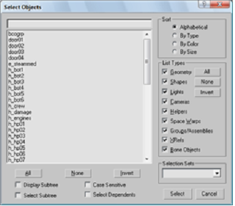
At this point, you should be able to see the model and its hardpoints in the editor. Use your mouse to click the Hardpoints tab, and then select the Hierarchy option. Upon doing this, your cursor will disappear, and you will have to use the keyboard to input commands. You should notice that there are a few "null" hardpoints. Before you continue, these should be deleted. On your keyboard, hit the number “3” and type “null01” (without quotes of course). The null01 hardpoint should disappear off the list. Continue deleting the null hardpoints until they are all gone.
Be careful not to delete anything else. Once they are all gone, the page should look like this.

This next part is very tedious and requires a lot of trial and error.
Hit escape to return to the model view. What you will now do is add a hardpoint and estimate its proper x,y,z coordinates. Prepare some scrap paper or a notepad document for documentation purposes.
First, click the Hardpoints tab, and select the Add One option. A new hardpoint labeled hp48 should appear at the center of your model.
Select the Hardpoints tab again, and click Move Selected. What you will now do is estimate the position of the right Bussard collector. You will place a single red glow there, and then one on the other side. Let's say that your initial guess was quite off, at about 100,-25,-500. However, your next guess was at 200,-100,-300, and was almost right on. By making a few more adjustments, you will end up at around 265,-75,-270.
Now that you have a single hardpoint in the right place, through basic geometry you will know that you can simply reverse the x value, and it will be at the other Bussard collector. Consequently, add another hardpoint and move it to -265,-75,-270. Knowing that the position of the glows will stay at about the same distance, left to right ( x-value) and might only need to be adjusted slightly up and down (y-value) you can make major adjustments just by changing the back and forth variables, or z values.
Now that you have the first two hardpoints, all you need to do now is add the rest along the nacelles themselves. They don’t have to be too close together, but you do want to keep them symmetrical. If you add one, and then just reverse the x variable to add one on the other side, then you shouldn’t have any problem keeping them in line.
Now you have hardpoints added in the right place, but nothing about them makes them glow since they are still just hardpoints.
Hierarchy
At this point, you may have two or more hardpoints added to the model. They will be named hp48, hp49, and so on. What you will need to do is add them to the Lights parent node, and give them names which correspond with sprite entries. For this purpose we will use the Saber classes’ Bussard collectors’ glows (Warpglowspritered6). What this means is that you will need to name the hardpoints s_Warpglowspritered6_1, and then _2. Note that this applies only to the red glows on the Bussards. The blue glows should have the name s_Warpglowspriteblue6_1, _2, etc.
Based on your preference, you may want to add additional lights to the Bussard collectors, or on either side of the nacelles to better imitate the light produced by warp engines.
Saving a Model
Saving your model in Assimsoft can be somewhat difficult. Adm. Zaxxon is not sure which button you actually need, but if you select the Hardpoints tab and click Lock In, and then in the same tab click Save To Dump-File, and lastly click the Object tab and click Save, it usually works.
Note that if you are unsure as to whether or not your work is saved, DO NOT close the program. The way to make sure your model was saved is to press the Windows button on your keyboard, open that object's folder again and check the modified date of your model. There will actually be two files in that folder now, but the one that is a .sod should be saved on the current date, and be of a similar size to the original SOD. In fact, it may be slightly larger in size.
Now you can go and test the model in-game, and if everything else is done properly it should show up something like this:
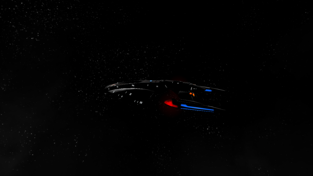
Note that the model shown above is not the same model you worked on, but is a properly light-mapped model with updated textures and other features by Jetfreak (the model is only available through MSFC). It does, however have the same glows that were added above, but only for the Bussard collectors.
Troubleshooting
Remember that you should feel free to post any problems on the forums. There are always those willing to help out with any problem you may be having.
The Unit Crashes the Game
This is most likely due to a misspelled hardpoint label, or a corrupt model. Make sure your names are all spelled correctly and you followed the saving procedure correctly.
The Unit is Invisible
This is because the ship was not saved correctly. You should be able to resave it in the editor with no problems.
3dsMax SOD Exporter
Path: Fleet Operations\Data\sod
Thank you for downloading and using the 3dsMax SOD Exporter Script. This script (and the following guide) was developed and written by Mr.Vulcan for the Armada community and works with all versions of 3dsMax and potentially with Gmax as well.
Version History
1.0 Original Release Jan 21, 2012
1.1 Bug Fix Jan 28, 2012
- The default save path name was changed to reflect the 3dsMax installation directory. The save path is now “*\3dsMaxRoot\meshes”
- Texture coordinate vertices are welded upon export. This does not affect the mesh quality, but can reduce the file size considerably. The 3dsMax5 plugin exporter contained this feature.
- Armada 2 model hierarchy no longer requires a “root” or “scene_root” node at the top of the hierarchy. This should improve compatibility with existing artwork.
1.2 Bug Fix Feb 11, 2012
- Allow multiple emitters with the same name (e_ename_01, e_ename_02... etc)
- Sprites and emitters can be animated directly without point helpers.
- Added rudimentary error handling to the script.
1.3 New features Feb 24, 2012
- Share materials between models and condense material ID’s by enumerating the materials in material editor.
1.4 Bug Fix Apr 7, 2012
- Fixed an animation export error when using “set key” function.
- Materials that can not be used in Armada are ignored (i.e., noise or parametric textures)
- Fixed an error that occasionally occurs when exporting the same model twice
- Other small bug fixes
1.5 Bug Fix: Dec 24, 2012
- Fixed a bug in handling of smoothing / lighting groups
- Added an extra check on texture face continuity to eliminate dark patches on A2 models
- Corrected an error in the documentation on smoothing / lighting material command node
Running the Exporter
Extract the script file(s) to a convenient folder and start up 3dsMax. A convenient folder might be "\scripts" or "\meshes" within the 3dsMax folder. When ready to export your model, click MAXScript -> Run Script... Alternatively, you can drag the script into the 3dsMax window.
Basic SOD Hierarchy
Armada 1: The top of the model hierarchy must have a "root" node. In order for the exporter to see your model, it must be attached to the model hierarchy tree. The standard hierarchy (root/geometry/model) will work just fine, but is not required. If so desired, one can attach all geometry directly to the root node.
Armada 2: A strict hierarchy is not required. If so desired, one can forego adding any hierarchy altogether. However, for good model organization, it is still recommended that a geometry node is added to contain all mesh objects, a hardpoints node is added to contain all hardpoints, etc.
If a model contains a "root" or "scene_root" nodes, everything attached to that node will be exported. Objects not attached to the hierarchy tree will not be exported. However, if a “root” or “scene_root” node is not supplied, everything in the scene will be exported (this includes hidden objects). The exporter does not support an export to selectionfeature at this time.
There are several reserved names that should only be used on nodes that require it.
|
Reserved Name
|
Description
|
Example
|
|
root / scene_root
|
Defines the top of the hierarchy tree
|
root
|
|
c_
|
Defines a command node. This node will not be exported, but will modify some parameter of its parent node
|
c_tm_alpha
c_anim_tex4x4_0.5
|
|
s_
|
Defines a sprite node
|
s_ redconst
|
|
e_
|
Defines an emitter node
|
e_ steamsml
|
|
Lod
|
Defines a lod control node
|
Lod1
|
It is good practice to attach "geometry", "lights", "hardpoints" and "damage" nodes to the "root" node. Attach all geometry meshes to the "geometry" node. All hardpoints to the “hardpoints” node. This will keep the hierarchy clean and pretty. However, do not add more nodes than you need. For example, if you are not adding damage effects, there is no reason to have the “damage” node or any of the system specific nodes.
Please note that the exporter will attempt to convert any geometry to an editable mesh before exporting.
The following image has an example of a completed hierarchy. The same hierarchy can be used in Armada 1 or Armada 2.

Lighting Materials
Armada uses lighting materials to define how a mesh will respond to lighting sources. Lighting materials are separate from texture materials, or render types. For example, you want one mesh to appear shiny, and another diffuse or matte. The way to do this is to create two lighting materials in the materials editor (MatShiny, MatMatte). For the shiny material, specify a specular color, level, and glossiness. For the matte material, you can set specular level to zero. For BOTH materials, specify the same texture file and then apply to different meshes. When you view the result in Armada, you will see that even though both meshes use the same texture, the material will look different.
In Armada, lighting materials have the following options:
|
Lighting Material Options
|
Description
|
|
Ambient Color
|
RGB color of the ambient light source. If set to black, model will be pitch black when no other light source is present (dark in space :P)
|
|
Diffuse Color
|
RGB color of the diffuse component. Normally this is set to White for textured models. However, you can change this by releasing the lock between Ambient and Diffuse components in the material editor.
|
|
Specular Color
|
RGB color of the specular reflections. If set to green, specular highlights will only reflect green. Normally set to grey.
|
|
Specular Level
|
Scale value between 0 – 100
|
|
Glossiness
|
Sharpness of the specular highlights. Minimum should be around 10.
|
|
Shader Type
|
Flat/Lambert/Phong. Automatically determined. For flat, set ambient color to white. For lambert, set specular level to zero. To set phong shader, avoid the above parameter values. Note that the default 3dsMax material will result in a Lambert shader.
|
Other parameters do not affect the SOD output. For texture materials, see Texture Materials.
A feature of this exporter is the ability to specify multiple lighting materials on a single mesh. By default, the whole mesh will use the lighting material that has been applied to the mesh in 3dsMax. However, you can change the lighting material for a specific smoothing group by attaching a "c_lm" node to the mesh. For example, if the 2nd smoothing group should use MatShiny, but all other smoothing groups should use MatMatte, you should assign MatMatte to the mesh, and use "c_lm_MatShiny_2" to assign the MatShinylighting material to smoothing group 2.
In similar fashion, you can assign a team color to the whole mesh, or to a specific smoothing group. To use team colors, prefix the lighting material name with "team_".
To use a single material with multiple textures, define all material properties in “mat_name_01”, and enumerate the remaining materials as “mat_name_##”. Only the first material will be defined in the SOD; the remaining materials will reference to the first. Non-enumerated materials will be exported as usual and should have unique names to avoid conflicts.
The following image shows the location of parameters of interest in the material editor (Max Version 5).
Smoothing Groups
The exporter now supports smoothing groups in an intuitive way. You may use the 3dsMax model smoothing groups to separate smoothing elements on a single mesh. Smoothing groups are also used as lighting material groups. This is discussed in the lighting materials section above.
Please note that the exporter will break vertices between smoothing group boundaries. This is necessary for proper rendering of smoothing groups in Armada. If you prefer to keep the vertices welded, please save the model before using the exporter. Reload the saved version after exporting to restore the model.

Texture Materials
Armada SODs support a single texture file per mesh. The texture file is the "Diffuse Map" in 3dsMax. In Armada 2, you can use the diffuse map to specify which parts of the mesh will glow (self illuminate) by linking the alpha component of the diffuse map with self illumination. In order to apply self-illumination to the model through the diffuse map, set the “self-illumination”map in the materials editor to use the same texture file as diffuse map. No other parameters need to be specified.
Bump maps can be added to the models in Armada 2 by specifying the "Bump map" in addition to the diffuse map. This should not generally be the same file as diffuse map. No other parameters need to be specified. Note that it is NOT possible to use a different texture file to specify the self-illumination map.
Command Nodes
The exporter has several features that may be set through command nodes. These are summarized in the following table
|
Command Type
|
Description
|
Example
|
|
c_anim
|
Defines a texture animation for the parent node and the animation starting time offset. Offset is optional, but should be specified if ambiguous. One per parent
|
c_anim_tex4x4_0.5
c_anim_tex4x4
c_anim_tex4x4_6_0.0
|
|
c_tm
|
Specifies render type. Can take on any of the render types shown below. Use only one per parent node
|
c_tm_additive
c_tm_alpha
|
|
c_lm
|
Specifies the lighting material to use and to which smoothing group to apply. This is explained in the lighting materials section
|
c_lm_SmoothGrp_MatName
c_lm_04_MaterialA
|
|
c_cull
|
Specifies whether to turn off backface culling. Default value is CullOn. This is an alternative to selecting “2-Sided” in the materials editor. One per parent.
|
c_cullOff
|
|
c_borg
|
Specifies a borg assimilation texture to use. (Armada 2 only) One per parent
|
c_borg_TexFile
c_borg_rassault_B
|
|
c_keys
|
Specifies the parent node animation length and number of keyframes
NumFrames parameter is optional. When specified, for best result, ensure that the number of keyframes, NumFrames,is divisible by animation length, Length.One per parent
|
c_keys_Length_NumFrames
c_keys_5_30
c_keys_5
|
Animation
SODs can be animated in 4 different ways
- Texture flip-book animation
- Translation animation
- Rotation animation
- Scale animation (Armada 2 only)
Texture animation: specified via sprite files. Some common animations are listed in tex_anim.spr. In order to apply this animation to a mesh, attach a "c_anim" node as specified in the command nodes table. Note that if the animation ID ends with an underscore, followed by a number, you should explicitly specify an animation offset. Otherwise, the exporter will interpret the numeric part as an offset rather than as part of the animation ID. For example, if the animation ID is tex4x4_2, you should name the command node as "c_anim_tex4x4_2_0.0".
Translation (motion along a line or curve) and Rotation (rotation around the pivot point): These types of animation must be key-based. That is, you can animate the model by setting keyframes. Other animation controllers are not supported. Also, translation and rotation animations are combined into a single channel for the SOD format. Therefore, translation and rotation animations will have the same length. Actual animation length is the longer of the two animation lengths.
Each animated node is recorded in a separate channel. Therefore, animations between different meshes will not be synchronized. This allows for much longer animation loops. You can control the length of animation in a channel through a "c_keys" node. To specify an animation length of 20 seconds, attach a "c_keys_20" node to the animated node.
Note that the default frame rate for translation and rotation animations is 18.3 frames per second. You can override the number of frames by specifying an additional parameter in "c_keys" node. To set the number of key frames to 2 (only two states will be shown, on/off for example), rename the previous command node to "c_keys_20_2". Please note that the animation is not interpolated between frames; ie, animation jumps from frame to frame with no blending.
Scale animation is supported by Armada 2 SODs in the same way as translation and rotation animation. However, scale animation is recorded in a separate channel and is not synchronized with translation and rotation.
One last note: you can apply an animation to any node; you do not have to animate just the mesh. Especially for rotation animations, it is far easier to attach the mesh to a "point_helper", and animate the point helper instead. In this way you can also set up a chain of animations.
Simple 3dsMax Animation
3dsMax is the only tool available to make animations in Armada 1 or 2 (Milkshape can also create animations, but unlike 3dsMax, there is no exporter for Armada). All images are from Max Version 5.
In order to start animating, you will need to load up a model in 3dsMax. The following image shows the how the screen should look once loaded:


First you will need to set the key amount (animation frames). It is best to use "Auto Keys" for this. Click Auto Key, which should turn the time line red and give you 30 frames:


Now it is time to select a mesh part. It is easier to do this by using "Select by Name" which is this button:
This will then open up a window like this:
Now, select the parts that you want to animate (it is best to do one mesh part at a time).
Once you have the part selected you can begin the animation.

First make sure the time slider is set to zero:

Lock the position for that frame (start position) by using the "Set Keys" button:

This ship will use just a simple ("door") animation, so you can now go to frame 30 (the final position). For more advanced animations you can lock the mesh positions at different intervals (this can also be used to slow animations and then for them to pick up speed mid animation).
The program automatically will fill in the intermediate positions of the mesh, so for this animation it is only necessary to set the start and end positions.
Once here you will need to move the mesh part to its final position and then lock it with the "Set Keys" button.
Repeat these steps until all parts have been done.

Note that if you want to convert a mesh you are working on from .ms3d to 3dsMax (to do animations and / or add a bump map before exporting into SOD format) it needs to be scaled up by 275%. This is especially important for animations, as the scaleSod ODF command can cause animation issues.
LOD Control
Armada uses LOD (level of detail) rendering when reducing the complexity of the scene.
You can add various levels of detail for your model if you are concerned about huge model complexity and you expect to have 10 of them on the screen at the same time all shooting phasers and such. Each LOD is a separate mesh. Therefore, you should model all levels of detail that you would need. There are 4 possible levels. Each LOD is a separate mesh; therefore, you should model all levels of detail that you would need.
Each LOD geometry should be attached to a “Lod” node, such that Lod 1 detail is "Lod1", Lod 2 detail is "Lod2".
The Lod nodes must be attached to "geometry", but otherwise the "geometry" root is not required at all. This behavior is hardcoded into Armada.
Texture Blending Modes
In addition to lighting materials, one has the option to specify a texture blending material. By default, textures are rendered opaque, with a hard cut-off for transparency. For example, if a texture has transparent parts, those parts will be transparent if the alpha value is less than 50%, and opaque if the alpha value is greater than 50%. Sometimes this behaviour is undesirable and can be modified according to these options:
|
Blending
|
Effect
|
|
default
|
Same as alphathreshold. Might render faster.
|
|
opaque
|
Ignores the alpha component. Not transparent.
|
|
nofilter
|
Does not stretch the texture when zoomed in. Makes texture look pixellated.
|
|
additive
|
Adds the RGB values to background. Makes object appear light and transparent.
|
|
add_nomipf
|
Unknown. Probably additive with no filter. Combination of the above two.
|
|
translucent
|
Unknown
|
|
atmosphere
|
Used on A2 atmospheres?
|
|
fog
|
Subtractive filter. Opposite effect to additive.
|
|
alphathreshold
|
Makes objects transparent below 50% alpha value.
|
|
wireframe
|
Renders the wireframe of the mesh.
|
|
interface
|
Used on all interface sprites. Similar to alphathreshold.
|
|
cloaked
|
Renders the mesh with the cloak effect.
|
|
wormhole
|
Unknown, but similar to alpha and used on wormholes.
|
|
alpha
|
Renders the semi-transparent textures properly (no cutoff).
|
|
alpha_nof
|
alphawith nofilter
|
To apply alpha blending to a mesh, attach a “c_tm” node such as "c_tm_alpha". To apply a cloak effect, attach a "c_tm_cloaked" node to the mesh.
SOD Viewer Storm3D tips
The Armada 2 Storm3D tool is rather less developed than the Armada 1 version. However, you may find that there are ways of making it work a little better for you:
- Press ‘F7’ once or twice (depending on your screen resolution) to increase the resolution of the rendering window. This is NOT the same as resizing the window. This makes it much easier to see detail.
- Press ‘s’ once or twice to lower the light intensity and turn the directional light to the left. This will allow you to view the glows much easier.
- Press ‘d’ to increase the LOD level. This only goes one way, does not lower the LOD level.
- Press ‘F6’ to view the damage effects (if present in the hierarchy). Toggles on/off.
3dsMax-SOD-Importer
Path: Fleet Operations\Data\sod
Thank you for downloading and using the 3dsMax SOD Importer Script. This script (and the following guide) was developed and written by Mr.Vulcan for the Armada community. Contact: tpankov (at) yahoo (dot) (ca)
WARNING!!
Use responsibly! Modding communities are built upon trust and respect for fellow modders. Please respect the work of those that came before you and seek permissions from authors before editing and releasing anything that is not personal work.
By using these scripts, you agree to abide by the “Don’t be a **** principle”. Cheers :)
Version History
1.0 Original Release Aug 27, 2013
1.0.1 Bug Fix Aug 30, 2013
Running the Importers
Extract the script file(s) to a convenient folder and startup 3dsMax. A convenient folder might be \scripts or \meshes within the 3dsMax folder.
There are 3 script files in the download.
SODImportBasic.ms – import SOD files for editing and exporting back to Armada.
SODImportRender.ms – import SOD files for rendering in 3dsMax.
SODImportSupport.ms – do not run. Contains common functions
Click MAXScript -> Run Script... Alternatively, you can drag the script into the 3dsMax window. You will be prompted to select a SOD for import. If the textures for the model are already in one of the directories that 3dsMax will search in for missing files, you are all set. Otherwise, you may want to use the alternate method described below.
The scripts may also run through the MAXScript Listener window for additional options. Run the script as described above and click cancel when prompted for the SOD file. Ignore the resulting error dialog. Now open the Listener by clicking MAXScript -> MAXScript Listener... or by pressing F11. On a new line at the very end of the white window, type:
ImportSOD FullFilePath:"F:\\Armada\\SOD\\fbattle.sod" TexturePath:"F:\\Armada\\textures\\rgb"
Please note the use of double backslash, \\, in path name. This is required by the MaxScript language. Replace the actual file path with the desired.
Known Issues
- At present, models with a large number of lighting materials (greater than 24) will not display the lighting materials in the materials editor. This in itself is not a bug, but a limitation in 3dsMax. However, there have been occasions when this issue caused an import error.
- The render script occasionally misinterprets self-illumination info from the SOD, using the alpha for transparency instead of self-illumination. Correct manually in the materials editor when encountering this problem.
- Some models may set the self-illumination level too low. Correct manually via materials editor.
- When using the importer multiple times during a single session, the following error may appear:
-- Error occurred in anonymous codeblock; filename:

		           D:\Taras\Dropbox\Armada\Transfers\Misc

		           Paperwork\Scripts\SODImportBasic4.ms; position:

		           678; line: 18

		-- Compile error: Can't find include file:  SODImportSupport.ms

		--  In line: include "SODImportSupport.ms"
The solution is to re-save the script by pressing ctrl+s while in the editor window (not the listener window):
Please report bugs any feature requests to the email address provided at the top, or on any of the official forum topics relating to these scripts (MSFC, AFC, FleetOps). Check back often for updates.